

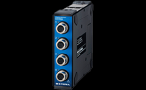
Strain/Voltage Unit CTRS-CDV010A
Add to Wishlist
Modular type for easy expansion and up to 128 channels High installation and flexibility Shock resistance: 490 m/s2 (50 G) All channels synchronous 20 kHz (For 4 channels) Measurement of 1 channel at max. 100 kHz Wireless real-time monitoring is possible
Availability:
1 in stock
Contact for a quote.
Request for Quotationช่องทางการสั่งซื้ออื่น ๆ
 ติดต่อทาง Line
@santatech
ติดต่อทาง Line
@santatech
 ติดต่อทางอีเมล์
santatech@gmail.com
ติดต่อทางอีเมล์
santatech@gmail.com
 ติดต่อทางโทรศัพท์
02-1013454
ติดต่อทางโทรศัพท์
02-1013454
Description
This Compact Recorder CTRS-100 Series is a compact, lightweight and impact-resistant construction, this can be applied to measurements of various stress in environments where exposed to vibrations and impact in limited spaces such as driving test of two-wheeled vehicles and on actual ships, and to measurements on table-tops.
Specifications
Channels 4Input Connector
| Connector Shape |
NDIS4109 (Small round 9 pins) receptacle Model: EPRC07-RX9FNDIS |
|---|---|
| Compatible Plug |
NDIS4109 (Small round 9 pins) plug Model: EPRC07-P9MNDIS |
| Measuring Targets |
[Strain measurement] Strain gages*1 Strain-gage transducers [Voltage measurement] Voltage |
|---|---|
| Compatible Bridge Resistance |
[Strain measurement] When bridge excitation is set to 2 V: 120 to 1000 Ω When bridge excitation is set to 5 V: 350 to 1000 Ω [Voltage measurement] N/A |
| Gage Factor |
[Strain measurement] 2.00 fixed [Voltage measurement] N/A |
| Bridge Excitation/Sensor Excitation |
[Strain measurement] 2, 5 VDC A maximum of 20 mA per channel can be output. [Voltage measurement] 2, 5 VDC*2, OFF(0 V) A maximum of 20 mA per channel can be output. |
| Input Impedance |
[Strain measurement] N/A [Voltage measurement] 3.6 MΩ ±10% |
| Input Modes |
[Strain measurement] Balanced differential input [Voltage measurement] Balanced differential input |
Measuring Range
| Setting Method |
[Strain measurement] Any range method or OFF [Voltage measurement] Any range method or OFF |
|---|---|
| Settable Range |
[Strain measurement] Minimum: 1000 × 10-6 strain Maximum: 50000 × 10-6 strain [Voltage measurement] Minimum: 1 V Maximum: 50 V |
| Setting Steps |
[Strain measurement] ・1000 to 10000 × 10-6 strain: 100 × 10-6 strain steps ・10000 to 50000 × 10-6 strain: 1000 × 10-6 strain steps [Voltage measurement] ・1 to 10 V: 0.1 V steps ・10 to 50 V: 1 V steps |
| Range Accuracy |
[Strain measurement] Within ±0.2% FS [Voltage measurement] Within ±0.2% FS |
|---|---|
| Nonlinearity |
[Strain measurement] Within ±0.1% FS [Voltage measurement] Within ±0.1% FS |
Temperature Stability
| Zero Point |
[Strain measurement] Within ±(0.009% FS + 0.9 × 10⁻⁶ strain)/°C [Voltage measurement] Within ±(0.009% FS + 0.21 mV)/°C |
|---|---|
| Sensitivity |
[Strain measurement] Within ±0.03%/°C [Voltage measurement] Within ±0.03%/°C |
Time Stability
| Zero Point |
[Strain measurement] Within ±(0.09% FS + 9 × 10⁻⁶ strain)/8 h [Voltage measurement] Within ±(0.09% FS + 0.1 mV)/8 h |
|---|---|
| Sensitivity |
[Strain measurement] Within ±0.3%/8 h [Voltage measurement] Within ±0.3%/8 h |
Balance Adjustment
| Setting |
[Strain measurement] For each channel, ON, OFF, or NONE can be selected. ON: Execute balance adjustment and set the measured value to zero. OFF: Do not execute balance adjustment again. NONE: Balance adjustment can be disabled to check the initial unbalanced value (Input voltage). [Voltage measurement] For each channel, ON, OFF, or NONE can be selected. ON: Execute balance adjustment and set the measured value to zero. OFF: Do not execute balance adjustment again. NONE: Balance adjustment can be disabled to check the initial unbalanced value (Input voltage). |
|---|---|
| Operating Method |
[Strain measurement] Execute the balance operation by using the control software*3 or operate the special-remote-control BAL switch. [Voltage measurement] Execute the balance operation by using the control software*3 or operate the special-remote-control BAL switch. |
| Adjustment Method |
[Strain measurement] Auto balance (Saved in nonvolatile memory) [Voltage measurement] Auto balance (Saved in nonvolatile memory) |
| Adjustment Range |
[Strain measurement] Within ±10000 × 10-6 strain [Voltage measurement] Within ±10 V |
| Accuracy |
[Strain measurement] Within ±(0.1% FS +2 × 10⁻⁶ strain) [Voltage measurement] Within ±0.1% FS |
| NONE Accuracy |
[Strain measurement] Within ±1% FS*4 [Voltage measurement] Within ±0.2% FS |
| Input Range |
[Strain measurement] Within ±60000 × 10-6 strain [Voltage measurement] Within ±60 V |
|---|---|
| Common-mode Input Voltage |
[Strain measurement] N/A [Voltage measurement] Within ±20 V |
Absolute Maximum Rating
| Input |
[Strain measurement] ±5 V [Voltage measurement] ±70 V |
|---|
| Frequency Response | DC to 20 kHz, -3 ±1 dB (At 20 kHz) |
|---|
LPF
| Transfer Characteristics | 5th-order Butterworth |
|---|---|
| Cutoff Frequency | 10, 20, 50, 100, 200, 500, 1k, 2k, 5k, 10k Hz as well as FLAT*5, AUTO*6 |
| Amplitude Ratio at Cutoff Point | -3 ±1 dB |
| Attenuation Characteristics | -30 ±3 dB/oct.*7 |
HPF
| Cutoff Frequency | 0.2, 1 Hz and OFF |
|---|
AD Conversion
| Resolution | 24 bits |
|---|---|
| Method | Synchronous sampling of all channels |
| Indicator | Status LED, channel-status LED |
|---|
Other Functions
| Input Resistance Check Functions |
Bridge resistance check function Accuracy within ±2% Used for sensor connection checks |
|---|---|
| TEDS | Read the TEDS information and apply it to the measurement conditions.*3 |
| Power Supply | Supplied by the CTRS-100A or CTRS-BATT010A |
|---|---|
| Power Consumption | Approx. 2.1 W (When supplying 12 VDC) |
| Operating Temperature | -10 to 50°C |
| Operating Humidity | 20 to 90% (Non-condensing) |
| Storage Temperature | -20 to 60°C |
| Vibration Resistance | 49.0 m/s2 (5 G), 5 to 200 Hz |
| Shock Resistance | 490 m/s2 (50 G), 11 ms or less, half sine wave |
| Dimensions |
26.6 W × 92 H × 94 D mm (Excluding protrusions and protectors) |
| Weight | Approx. 240 g |
| Utility Nuts | Size: M4, 6 places |
|
* The measuring unit specifications apply to the state in which the temperature has stabilized after a preheating time of 30 minutes. *1 A separate bridge box is necessary. *2 When the sensor excitation is 2 VDC, the positive side of the sensor excitation is +1 V and the negative side is -1 V. When the sensor excitation is 5 VDC, the positive side of the sensor excitation is +2.5 V and the negative side is -2.5 V. *3 Only when online control is performed by a PC. *4 When the bridge resistance is 350 Ω *5 When FLAT is set, the cutoff frequency is set to approx. 25 kHz. However, the cutoff point amplitude ratio specification is not applied. *6 When AUTO is set, the cutoff frequency is set to approx. 1/4 the specified sampling frequency. *7 Excluding cutoff frequencies over 5 kHz |
| Standard Accessories |
Stack-connector cap (female) Stack-connector cap (male) Input connector caps × 4 |
|---|---|
| Optional Accessories |
4109P-S32-7 (4-conductor shielded) N-129 4109P-S32-7 (6-conductor shielded) U-136 4109P-BNC plug U-137 4109P-BNC jack U-129 4109P-R05 jack U-138 |
SANTA TECHNOLOGY CO.,LTD. (Head Office)
35/218 Moo. 2, Leabkhlongsam Rd., Khlongsam, Khlongluang, Pathumthani 12120
Call 02-101-3454 ,089-006-2766
Fax 02-101-3453
Mail. santatech@gmail.com
Line : @santatech
Web : https://santatechnology.com/
