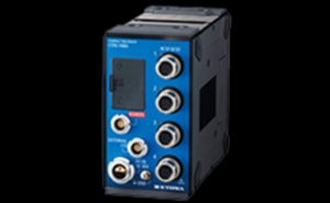
เครื่องบันทึกภาพขนาดกะทัดรัด CTRS-100 Series นี้มีโครงสร้างที่กะทัดรัด น้ำหนักเบา และทนต่อแรงกระแทก ใช้ได้กับการวัดความเครียดต่างๆ ในสภาพแวดล้อมที่ต้องเผชิญกับการสั่นสะเทือนและแรงกระแทกในพื้นที่จำกัด เช่น การทดสอบการขับขี่ยานพาหนะสองล้อและการใช้งานจริง เรือและการวัดบนโต๊ะ
ข้อมูลจำเพาะ
ข้อมูลจำเพาะของหน่วยควบคุม
ตัวเชื่อมต่อ
|
ขั้วต่อ USB
|
ไมโคร USB Type-B
|
|
ขั้วต่อรีโมทคอนโทรล
|
ใช้สำหรับเชื่อมต่อชุดรีโมทคอนโทรล
|
|
ขั้วต่อ I/O ภายนอก
|
รุ่น: ECA.0B.307.CLN
ขั้วต่อที่ใช้ร่วมกันได้: FGA.0B.307.CLAD52
|
|
สวิตช์ปฏิบัติการ
|
พลัง
|
|
จอแสดงผลยูนิตหลัก
|
ไฟ LED แสดงสถานะ
การเข้าถึงการ์ด SD LED
|
|
สื่อบันทึกข้อมูล
|
มาตรฐาน SD การ์ด SD สำหรับใช้ในอุตสาหกรรมแนะนำ
: ความจุ SDHC
: 4 GB,
รูปแบบ 16 GB: FAT32
(ไม่รับประกันการทำงานหากใช้การ์ด SD อื่นนอกเหนือจากผลิตภัณฑ์ที่แนะนำ)
|
|
อินเทอร์เฟซการสื่อสาร
|
อีเธอร์เน็ตUSB (USB2.0 ความเร็วสูง) *1 (10/100BASE-T)
|
จำนวนยูนิตที่สามารถเชื่อมต่อได้
|
หน่วยวัด
|
สามารถเชื่อมต่อได้สูงสุด 7 ยูนิตต่อ CTRS-100A
(รวม 32 ช่อง)
|
|
ยูนิตขยาย
|
สามารถเชื่อมต่อได้สูงสุด 5 ยูนิตต่อ CTRS-100A
อย่างไรก็ตาม ไม่สามารถเชื่อมต่อและใช้งานยูนิตเดียวกันตั้งแต่ 2 เครื่องขึ้นไปได้
|
การซิงโครไนซ์ระหว่างอุปกรณ์
|
วิธีการซิงโครไนซ์
|
ใช้ยูนิตซิงโครไนซ์และสายเคเบิลซิงโครนัสเพื่อเชื่อมต่อยูนิต CTRS-100A
|
|
จำนวนหน่วยสูงสุดที่สามารถซิงโครไนซ์ได้
|
สูงสุดคือสี่หน่วย CTRS-100A และสามารถซิงโครไนซ์ช่องการวัดสูงสุด 128 ช่อง
|
|
ข้อมูลที่บันทึกไว้
|
ข้อมูลจะถูกบันทึกลงในการ์ด SD ของแต่ละยูนิตหรือพีซี *2
|
ข้อมูลที่บันทึกไว้
|
ตำแหน่งการบันทึกไฟล์
|
พีซีการ์ด SD *2
|
|
รูปแบบข้อมูล
|
รูปแบบมาตรฐานของเคียวว่า KS3
|
|
ขนาดไฟล์ข้อมูลสูงสุด
|
4 GB/1 ไฟล์ข้อมูล
(1 GB = 1000000000 ไบต์) *3
|
|
การเก็บรวบรวมข้อมูล
|
การรวบรวมออนไลน์ : รวบรวมโดยซอฟต์แวร์ควบคุม (PC) การ
รวบรวมออฟไลน์ : รวบรวมโดยการอ่านข้อมูลโดยตรงจากการ์ด SD ไปยังพีซี
|
วิธีการตั้งค่าเงื่อนไขการวัด
|
การตั้งค่าออนไลน์
|
กำหนดโดยซอฟต์แวร์ควบคุม (PC)
|
|
การตั้งค่าออฟไลน์
|
กำหนดโดยการอ่านการตั้งค่าเงื่อนไขการวัดในการ์ด SD
|
โหมดบันทึก
|
คู่มือ
|
ผู้ใช้ดำเนินการเพื่อเริ่มหรือหยุดการบันทึก
|
|
ทริกเกอร์ (ทริกเกอร์แบบผสม)
|
การบันทึกอัตโนมัติจะดำเนินการตามการตั้งค่าเงื่อนไขทริกเกอร์
|
|
ช่วงเวลา
|
การบันทึกอัตโนมัติจะดำเนินการตามเวลาเริ่มต้นการบันทึกและการตั้งค่าช่วงเวลาการบันทึก
|
สุ่มตัวอย่าง
|
วิธี
|
การสุ่มตัวอย่างแบบซิงโครนัสของทุกช่อง
|
|
ความถี่
|
[1-2-5 ซีรีส์]
1, 2, 5, 10, 20, 50, 100, 200, 500, 1k, 2k, 5k, 10k, 20k, 50k, 100k Hz
[2 nซีรีส์]
4, 8, 16 , 32, 64, 128, 256, 512, 1024, 2048, 4096, 8192, 16384, 32768, 65536 Hz
ความถี่สุ่มสูงสุดที่สามารถตั้งค่าได้:
100 kHz / จำนวนช่องการวัด
|
|
นาฬิกาภายนอก
|
อินพุตนาฬิกาจากอุปกรณ์ภายนอกใช้เป็นนาฬิกาสุ่มตัวอย่าง
ความถี่ตั้งแต่ 1 Hz ถึง 100 kHz สามารถตั้งค่าได้ทีละ 1-Hz
ป้อนนาฬิกาภายในช่วงความถี่ที่ระบุ ±5%
ระดับแรงดันไฟฟ้า: แรงดันไฟฟ้าระดับ
สูง 2.4 ถึง 5 V
แรงดันไฟฟ้าระดับต่ำ 0 ถึง 0.8 V
หน้าที่: 30 ถึง 70%
|
ฟังก์ชันทริกเกอร์
|
ประเภททริกเกอร์
|
・สัญญาณอินพุตแบบอะ
นาล็อก (ทริกเกอร์แบบอะนาล็อก)
・สัญญาณอินพุตทริกเกอร์ภายนอก
(หน้าสัมผัสไม่มีแรงดัน, โอเพ่นคอลเลคเตอร์, สัญญาณที่มีแรงดันไฟฟ้าระดับสูง 2.4 ถึง 5 V และแรงดันไฟฟ้าระดับต่ำ 0 ถึง 0.8 V)
・แบบแมนนวล
(หากปุ่ม REC เป็น กดในทริกเกอร์รอสถานะ การบันทึกเริ่มต้น)
|
|
ระดับทริกเกอร์
|
สามารถตั้งค่าระดับใดก็ได้ภายในช่วง ±FS *4
|
|
ทริกเกอร์ลาด
|
ความชัน (บวก), ความชัน (เชิงลบ)
|
|
ทริกเกอร์ล่วงหน้า
|
ระบุจำนวนข้อมูลที่จะบันทึกก่อนจุดเริ่มต้น
สามารถตั้งค่ารายการข้อมูลได้สูงสุด 524288 รายการ/จำนวนช่องการวัด
|
|
โพสต์ทริกเกอร์
|
ระบุจำนวนข้อมูลที่จะบันทึกหลังจากจุดสิ้นสุดของทริกเกอร์
สามารถตั้งค่ารายการข้อมูลได้สูงสุด 524288 รายการ/จำนวนช่องการวัด
|
ฟังก์ชั่นสำรอง
|
เป้าหมายสำรอง
|
เงื่อนไขการตั้งค่า, ค่าการปรับสมดุล (ค่าระงับศูนย์)
|
|
กำลังบันทึกตำแหน่ง
|
หน่วยความจำแบบไม่ลบเลือนภายใน
|
เอาต์พุตนาฬิกาภายนอก
|
ระดับสัญญาณ
|
5 VDC
สามารถตั้งค่าสัญญาณกลับด้านหรือไม่กลับด้านได้
|
|
แผนก
|
สัญญาณนาฬิกาที่ซิงโครไนซ์กับนาฬิกาสุ่มตัวอย่างจะถูกแบ่งออกและส่งออก
สามารถกำหนดอัตราส่วนการหารในช่วง 1 ถึง 65534 ได้
|
|
โหมดเอาต์พุต
|
เลือกจากเอาต์พุตนาฬิกาเสมอ ส่งออกขณะบันทึกเท่านั้น หรือไม่ส่งออกเลย
|
ฟังก์ชั่นอื่นๆ
|
ข้อมูลจำเพาะของจำนวนรายการข้อมูลที่จะบันทึก
|
เมื่อบันทึกรายการข้อมูลตามจำนวนที่ระบุแล้ว การบันทึกจะเสร็จสิ้นโดยอัตโนมัติ
|
|
ฟังก์ชันการกู้คืนอัตโนมัติเมื่อไฟฟ้าขัดข้อง*5
|
ขณะบันทึก หากแหล่งจ่ายไฟถูกขัดจังหวะเนื่องจากไฟฟ้าดับ ฯลฯ คุณสามารถเลือกได้ว่าจะเปลี่ยนไปใช้พลังงานจากแบตเตอรี่และดำเนินการบันทึกต่อหรือปิดไฟล์ที่กำลังบันทึกแล้วปิดตัวลง
หากเลือกตัวเลือกในการปิดเครื่อง คุณสามารถเลือกได้ว่าจะทำการบันทึกต่อหลังจากที่เปิดเครื่องแล้วหรือเข้าสู่สถานะสแตนด์บาย
|
|
การบันทึกฟังก์ชันการกู้คืน
|
คุณสามารถเลือกได้ว่าจะทำการบันทึกต่อหรือเข้าสู่สถานะสแตนด์บายเมื่อปิดสวิตช์ POWER ขณะบันทึกแล้วเปิดขึ้นมาใหม่
|
|
การกำหนดชื่อไฟล์
|
กำหนดหมายเลขไฟล์หรือวันที่บันทึกให้กับชื่อไฟล์ข้อมูลที่บันทึกโดยอัตโนมัติ
|
|
เอาต์พุตสัญญาณทริกเกอร์
|
ส่งสัญญาณทริกเกอร์เมื่ออยู่ในโหมดบันทึกทริกเกอร์ (ทริกเกอร์แบบผสม)
ขณะสแตนด์บาย: 5 VDC
ขณะบันทึก: 0 VDC
|
ข้อมูลจำเพาะของหน่วยวัด
ช่องเสียบอินพุต
|
รูปร่างตัวเชื่อมต่อ
|
[การวัดความเครียด]
NDIS4109 (รอบเล็ก 9 พิน) เต้ารับ
รุ่น: EPRC07-RX9FNDIS
[การวัดแรงดัน]
NDIS4109 (รอบเล็ก 9 พิน) เต้ารับ
รุ่น: EPRC07-RX9FNDIS
|
|
ปลั๊กที่ใช้ร่วมกันได้
|
[การวัดความเครียด]
ปลั๊ก NDIS4109 (หมุดกลมเล็ก 9 ขา)
รุ่น: EPRC07-P9MNDIS
[การวัดแรงดันไฟฟ้า]
ปลั๊ก NDIS4109 (หมุดกลมเล็ก 9 ขา)
รุ่น: EPRC07-P9MNDIS
|
|
เป้าหมายการวัด
|
[การวัดความเครียด] ส
เตรนเกจ*6
ทรานสดิวเซอร์สเตรนเกจ
[การวัดแรงดัน]
แรงดันไฟ
|
|
ความต้านทานสะพานที่เข้ากันได้
|
[การวัดความเครียด]
เมื่อตั้งค่าการกระตุ้นสะพานเป็น 2 V: 120 ถึง 1000 Ω
เมื่อตั้งค่าการกระตุ้นสะพานเป็น 5 V: 350 ถึง 1000 Ω
[การวัดแรงดันไฟฟ้า]
N/A
|
|
เกจแฟกเตอร์
|
[การวัดความเครียด]
2.00 คงที่
[การวัดแรงดันไฟฟ้า]
N/A
|
|
สะพานกระตุ้น/กระตุ้นเซ็นเซอร์
|
[การวัดความเครียด]
2, 5 VDC
เอาต์พุตสูงสุด 20 mA ต่อช่องสัญญาณ
[การวัดแรงดันไฟฟ้า]
2, 5 VDC *7 , OFF (0 V)
สามารถเอาท์พุตได้สูงสุด 20 mA ต่อช่องสัญญาณ
|
|
อิมพีแดนซ์อินพุต
|
[การวัดความเครียด]
N/A
[การวัดแรงดันไฟฟ้า]
3.6 MΩ ± 10%
|
|
โหมดอินพุต
|
[การวัดความเครียด]
อินพุทดิฟเฟอเรนเชียลที่สมดุล
[การวัดแรงดัน]
อินพุทดิฟเฟอเรนเชียลที่สมดุล
|
ช่วงการวัด
|
วิธีการตั้งค่า
|
[การวัดความเครียด]
วิธีช่วงใดๆ หรือ OFF
[การวัดแรงดันไฟฟ้า]
วิธีช่วงใดๆ หรือ OFF
|
|
ช่วงที่กำหนดได้
|
[การวัดความเครียด]
ขั้นต่ำ: 1000 × 10 -6ความเครียด
สูงสุด: 50000 × 10 -6ความเครียด
[การวัดแรงดันไฟฟ้า]
ขั้นต่ำ: 1 V
สูงสุด: 50 V
|
|
ขั้นตอนการตั้งค่า
|
[การวัดความเครียด]
・1,000 ถึง 10,000 × 10 -6ความเครียด: 100 × 10 -6ความเครียดขั้น
・10000 ถึง 50000 × 10 -6ความเครียด: 1,000 × 10 -6ความเครียดขั้น
[การวัดแรงดันไฟฟ้า]
・1 ถึง 10 V: 0.1 V ขั้นตอน
・10 ถึง 50 V: 1 V ขั้นตอน
|
|
ความแม่นยำของช่วง
|
[การวัดความเครียด]
ภายใน ±0.2% FS
[การวัดแรงดันไฟฟ้า]
ภายใน ±0.2% FS
|
|
ความไม่เชิงเส้น
|
[การวัดความเครียด]
ภายใน ±0.1% FS
[การวัดแรงดันไฟฟ้า]
ภายใน ±0.1% FS
|
ความเสถียรของอุณหภูมิ
|
จุดศูนย์
|
[การวัดความเครียด]
ภายใน ±(0.009% FS + 0.9 × 10 -6ความเครียด)/°C
[การวัดแรงดันไฟฟ้า]
ภายใน ±(0.009% FS + 0.21 mV)/°C
|
|
ความไว
|
[การวัดความเครียด]
ภายใน ±0.03%/°C
[การวัดแรงดันไฟฟ้า]
ภายใน ±0.03%/°C
|
ความเสถียรของเวลา
|
จุดศูนย์
|
[การวัดความเครียด]
ภายใน ±(0.09% FS + 9 × 10 -6ความเครียด)/8 ชม.
[การวัดแรงดันไฟฟ้า]
ภายใน ±(0.09% FS + 0.1 mV)/8 ชม.
|
|
ความไว
|
[การวัดความเครียด]
ภายใน ±0.3%/8ชม.
[การวัดแรงดันไฟฟ้า]
ภายใน±0.3%/8ชม.
|
ปรับสมดุล
|
การตั้งค่า
|
[การวัดความเครียด]
สำหรับแต่ละช่อง เลือก ON, OFF, หรือ NONE ได้
เปิด: ดำเนินการปรับสมดุลและตั้งค่าที่วัดได้เป็นศูนย์
ปิด: อย่าดำเนินการปรับสมดุลอีกครั้ง
ไม่มี: สามารถปิดใช้งานการปรับบาลานซ์เพื่อตรวจสอบค่าเริ่มต้นที่ไม่สมดุล (แรงดันไฟเข้า)
[การวัดแรงดันไฟฟ้า]
สามารถเลือกเปิด ปิด หรือ NONE แต่ละช่องได้
เปิด: ดำเนินการปรับสมดุลและตั้งค่าที่วัดได้เป็นศูนย์
ปิด: อย่าดำเนินการปรับสมดุลอีกครั้ง
ไม่มี: สามารถปิดใช้งานการปรับบาลานซ์เพื่อตรวจสอบค่าเริ่มต้นที่ไม่สมดุล (แรงดันไฟเข้า)
|
|
วิธีการใช้งาน
|
[การวัดความเครียด]
ใช้งานเครื่องชั่งโดยใช้ซอฟต์แวร์ควบคุม*2หรือใช้งานสวิตช์ BAL รีโมทคอนโทรลพิเศษ
[การวัดแรงดันไฟฟ้า]
ดำเนินการเกี่ยวกับเครื่องชั่งโดยใช้ซอฟต์แวร์ควบคุม*2หรือใช้งานสวิตช์ BAL รีโมทคอนโทรลพิเศษ
|
|
วิธีการปรับ
|
[การวัดความเครียด]
สมดุลอัตโนมัติ (บันทึกไว้ในหน่วยความจำแบบไม่ลบเลือน)
[การวัดแรงดันไฟฟ้า]
สมดุลอัตโนมัติ (บันทึกไว้ในหน่วยความจำแบบไม่ลบเลือน)
|
|
ช่วงการปรับ
|
[การวัดความเครียด]
ภายใน ±10000 × 10 -6ความเครียด
[การวัดแรงดันไฟฟ้า]
ภายใน ±10 V
|
|
ความแม่นยำ
|
[การวัดความเครียด]
ภายใน± (0.1% FS + 2 × 10 -6ความเครียด)
[การวัดแรงดันไฟฟ้า]
ภายใน± 0.1% FS
|
|
ไม่มีความแม่นยำ
|
[การวัดความเครียด]
ภายใน ±1% FS *8
[การวัดแรงดันไฟฟ้า]
ภายใน ±0.2% FS
|
|
ช่วงอินพุต
|
[การวัดความเครียด]
ภายใน ±60000 × 10 -6ความเครียด
[การวัดแรงดันไฟฟ้า]
ภายใน ±60 V
|
|
แรงดันไฟฟ้าอินพุตโหมดทั่วไป
|
[การวัดความเครียด]
N/A
[การวัดแรงดันไฟฟ้า]
ภายใน ±20 V
|
คะแนนสูงสุดแอบโซลูท
|
ป้อนข้อมูล
|
[การวัดความเครียด]
±5 V
[การวัดแรงดันไฟฟ้า]
±70 V
|
|
การตอบสนองความถี่
|
DC ถึง 20 kHz, -3 ±1 dB (ที่ 20 kHz)
|
LPF
|
ลักษณะการโอน
|
อันดับที่ 5 บัตเตอร์เวิร์ธ
|
|
ตัดความถี่
|
10, 20, 50, 100, 200, 500, 1k, 2k, 5k, 10k Hz เช่นเดียวกับ FLAT *9 , AUTO *10
|
|
อัตราส่วนแอมพลิจูดที่จุดตัด
|
-3 ±1 dB
|
|
ลักษณะการลดทอน
|
-30 ±3 เดซิเบล/ต.ค. *11
|
HPF
|
ตัดความถี่
|
0.2, 1 Hz และ OFF
|
การแปลงโฆษณา
|
ปณิธาน
|
24 บิต
|
|
วิธี
|
การสุ่มตัวอย่างแบบซิงโครนัสของทุกช่อง
|
|
อินดิเคเตอร์
|
LED สถานะช่อง
|
ฟังก์ชั่นอื่นๆ
|
ฟังก์ชันตรวจสอบความต้านทานอินพุต
|
ฟังก์ชันตรวจสอบความต้านทานบริดจ์ ความ
แม่นยำภายใน ±2%
ใช้สำหรับตรวจสอบการเชื่อมต่อเซ็นเซอร์
|
|
TEDS
|
อ่านข้อมูล TEDS และนำไปใช้กับเงื่อนไขการวัด *2
|
ข้อมูลจำเพาะทั่วไป
|
ขั้วต่อสายไฟ
|
รุ่น: ECP.1S.302.CLL
|
|
พาวเวอร์ซัพพลาย
|
10 ถึง 30 VDC
|
|
การใช้พลังงาน
|
ประมาณ 3.5 W (เมื่อจ่ายไฟ 12 VDC)
|
|
อุณหภูมิในการทำงาน
|
-10 ถึง 50°C
|
|
ความชื้นในการทำงาน
|
20 ถึง 90% (ไม่กลั่นตัว)
|
|
อุณหภูมิในการจัดเก็บ
|
-20 ถึง 60°C
|
|
ความต้านทานการสั่นสะเทือน
|
49.0 ม./วินาที2 (5 G), 5 ถึง 200 Hz
|
|
กันกระแทก
|
490 ม./วินาที2 (50 G), 11 ms หรือน้อยกว่า, ฮาล์ฟไซน์เวฟ
|
|
ขนาด
|
53.2 W × 92 H × 94 D มม.
(ไม่รวมส่วนที่ยื่นออกมาหรือตัวป้องกัน)
|
|
น้ำหนัก
|
ประมาณ 420 กรัม
|
|
เทอร์มินัล
|
ขั้ว GND: M3 ผูก
|
|
ถั่วยูทิลิตี้
|
ขนาด: M4, 12 ตำแหน่ง
|
|
|
* ข้อมูลจำเพาะของหน่วยวัดใช้กับสถานะที่อุณหภูมิคงที่หลังจากเวลาอุ่นเครื่อง 30 นาที
*1 จำเป็นต้องมียูนิตซิงโครไนซ์แยกต่างหากและสายเคเบิลสื่อสารพิเศษ
*2 เฉพาะเมื่อควบคุมออนไลน์โดยพีซีเท่านั้น
*3 เวลาในการบันทึกสูงสุดขึ้นอยู่กับจำนวนช่องการวัดและความถี่ในการสุ่มตัวอย่าง
เวลาในการบันทึกสูงสุด : 1000000000 ÷ จำนวน
ช่องการวัด ÷ ความถี่ในการสุ่มตัวอย่าง
*4 สัญญาณอินพุตแบบอะนาล็อกเท่านั้น
*5 เมื่อเชื่อมต่อชุดแบตเตอรี่เท่านั้น
*6 จำเป็นต้องใช้กล่องบริดจ์แยกต่างหาก
*7 เมื่อเซ็นเซอร์กระตุ้นเป็น 2 VDC ด้านบวกของการ
กระตุ้นเซ็นเซอร์คือ + 1 V และด้านลบคือ -1V
เมื่อเซ็นเซอร์กระตุ้นเป็น 5 VDC ด้านบวกของ
แรงดันกระตุ้นเซ็นเซอร์คือ +2.5 V และด้านลบคือ -2.5 V
*8 เมื่อความต้านทานของบริดจ์อยู่ที่ 350 Ω
*9 เมื่อตั้งค่า FLAT ความถี่ตัดจะถูกตั้งค่า ประมาณ 25 เฮิร์ทซ์
อย่างไรก็ตาม ไม่มีการปรับใช้ข้อกำหนดอัตราส่วนแอมพลิจูดของจุดตัดจุดตัด
*10 เมื่อตั้งค่า AUTO ความถี่ตัดจะถูกตั้งไว้ที่ประมาณ 1/4 ความถี่สุ่มตัวอย่างที่ระบุ
*11 ไม่รวมความถี่ตัดที่เกิน 5 kHz
|
|
อุปกรณ์มาตรฐาน
|
ฝาครอบขั้วต่อสแต็ค (ตัวเมีย) ×2
การ์ด SD (4 GB)
สาย USB
CTRS สายไฟ DC P-79
สายกราวด์ P-78
ไขควงปากกาลูกลื่น
ฝาปิดขั้วต่ออินพุต ×4
|
|
อุปกรณ์เสริม
|
อะแดปเตอร์ AC CTRS UIA345-12-L-JP
(สำหรับสหรัฐอเมริกา: UNI345-1238-L-US)
หน่วยวัด
ต่างๆ หน่วยส่วนขยายต่างๆ ชุด
ควบคุมระยะไกล ฝาปิดขั้วต่อ
BRA.0B.200.PCSG
ฝาปิดขั้วต่อ BRA.1B.200.PCSG
4109P -S32-7 (หุ้มฉนวน 4 ตัวนำ) N-129
4109P-S32-7 (หุ้มฉนวน 6 ตัวนำ) U-136
4109P-BNC ปลั๊ก U-137
4109P-BNC แจ็ค U-129
4109P-R05 แจ็ค U-138
ภายนอก I /สายเคเบิล O การ์ด SD U-133
(4 GB)
การ์ด SD (16 GB) RP-SDFC16SW1
Dynamic Data Acquisition Software DCS-100A
(โปรดใช้เวอร์ชันล่าสุด)
|


 ติดต่อทาง Line
@santatech
ติดต่อทาง Line
@santatech
 ติดต่อทางอีเมล์
santatech@gmail.com
ติดต่อทางอีเมล์
santatech@gmail.com
 ติดต่อทางโทรศัพท์
02-1013454
ติดต่อทางโทรศัพท์
02-1013454