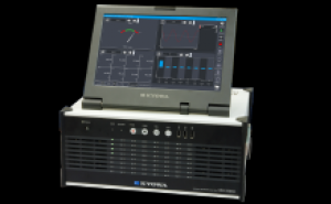
High-speed sampling at 200 kHz/32 channelsUp to 80 input channelsSimultaneous recording of measuring data and videoConditioner cards selectable for specific applicationsEffective real-time processing capability
EDX-5000A is an advanced all-in-one measuring instrument having sophisticated features and high-speed processing capabilities.
It is the high-end model of EDX Series
Specifications
Model
EDX-5000A-64-HE: Hard disk drive (HDD) , English
EDX-5000A-64-SE: Solid state drive (SSD) , English
1 channel (To be recorded together with measuring data.)
An optional remote control unit RCU-42 is required.
Sampling Frequencies
Sampling System
Simultaneous sampling of all channels
Sampling Frequencies
1-2-5 series
1 Hz to 200 kHz: When recording data up to 32 channels (16 channels)
1 Hz to 100 kHz: When recording data up to 64 channels (32 channels)
1 Hz to 50 kHz: When recording data up to 80 channels (64 channels)
1 Hz to 20 kHz: When recording data up to 80 channels (80 channels)
1 Hz to 10 kHz: When real-time simultaneous process is enabled
2n series
2 Hz to 131.072 kHz: When recording data up to 32 channels (16 channels)
2 Hz to 65.536 kHz: When recording data up to 64 channels (32 channels)
2 Hz to 32.768 kHz: When recording data up to 80 channels (64 channels)
2 Hz to 16.384 kHz: When recording data up to 80 channels (80 channels)
2 Hz to 8.192 kHz: When real-time simultaneous process is enabled
[Note] AD data format: In 16-bit mode
[Note] In the 24-bit mode, the number of channels mentioned in parentheses.
Data Storage Device
Hard Disk Drive (HDD) Capacity: 300 GB or more
Solid State Drive (SSD) Capacity: 30 GB or more
Display
Channel status LED (OVER value of every channel is settable)
REC, BUSY, BATTERY, POWER LED
With 12.1-inch wide touch panel mounted display
Operation Keys
Touch panel and front mounted keys(REC, STOP, BAL., OPT).
Operation with external keyboard and mouse is also possible.
External Control Connectors
CONT IN, CONT OUT (remote control,synchronous operation)
External I/O Connectors
External triggers: TRG IN, TRG OUT
External clock: CLK IN, CLK OUT
(Output at any frequency division ratio)
External Interfaces
USB type keyboard
USB type mouse
VGA connector for monitor
USB I/F: 3 USB 2.0 in front, 2 USB 3.0 in rear
*The USB 2.0 port in the front is limited to about 100 mA that can be supplied.
LAN I/F: 100/1000BASE-T
Power Supply
100 to 240 VAC and 10 to 30 VDC, dual supply
Built-in batteries against momentary power failure
Current Consumption
Approx. 1.8 A
(For 100 VAC, CDV-40B x 8)
Operating Temperature
0 to 40 ºC
Operating Humidity
20 to 80% (Non-condensing)
Storage Temperature
-20 to 60 ºC
Vibration Resistant
[EDX-5000A-64-HE, EDX-5000A-64-SE]
49.0 m/s2 (5 G), 5 to 55 Hz (When not operating)
29.4 m/s2 (3 G), 5 to 55 Hz (When operating)
AC power cable P-18 (With 2-pin conversion plug CM-52)
DC power cable P-70
Ground wire P-72
Simplified instruction manual
CD-R (Instruction manual)
EDX accessory bag
AC fuse
DC fuse
Soldering plug for DIO
Shell case for DIO plug
Optional Accessories
Synchronous cable N-128
Remote control unit RCU-42A
Belt hook
Dummy panel for EDX EDX1P-DUMMY
EDX2000-DUMMY
Software ETA-55A Specifications
Measuring Condition Settings
Measuring Channel Conditions
Measurement ON/OFF
Measuring modes
Range
HPF
LPF
Digital HPF
Digital LPF
Balance ON/OFF
CAL
Calibration coefficient
Offset
Offset zero ON/OFF
Unit
Channel name
Measuring range
Rated capacity
Rated output
Upper-limit check value
Lower-limit check value
Numeric display digits (Selects any items to display)
Inner sensitivity register ON/OFF
Input cable
Cable compensation value
Recordable Data
Up to remaining disk space of built-in memory
Manual Measurement
Recording from REC to STOP, or preset data starts from REC
Interval Measurement
Automatic recording according to designated starting time and recording interval
Trigger Measurement
Recording and stopping according to preset trigger conditions
• Common trigger conditions
End trigger: Settable
Pre-trigger: Max. 2097152 points per channel
Post-trigger: Max. 2097152 points per channel
(When AD is set to 24 bits)
Trigger data correlates with the number of channels and the AD data.
• Analog trigger conditions
Trigger channels: Any 1 analog channel
Trigger level: Sets in physical quantity.
Trigger slope: Up, down
• Digital trigger conditions
Trigger bit: Any 1 bit
Trigger level: 0, 1
• External trigger conditions
Trigger slope: Up, down
• Complex trigger conditions
Trigger source:
Selection of any 4 analog/digital channels, an external trigger channel, or a manual trigger channel
AND/OR:
Be used for analog trigger, digital trigger and external trigger.
Trigger level:
An physical quantity is set for the analog channel, and 0 or 1 for the digital channel.
Trigger slope: Up, down
TEDS
Reads sensor's information and sets to channel condition automatically.
Load/Save Measurement Conditions File
Load ME5 file and configure settings according to loaded measurement conditions.
Save the measurement conditions in ME5 file.
*You can also load/save ME5 file using DCS-100A and EDX-3000B COMPATIBLE SOFTWARE.
Measuring Operations
Monitor measurement, recording start, pause, stop, balancing, CAL output, etc.
Real-time Processing
Simultaneous monitoring and recording of data
The sampling frequencies up to 10 kHz are available.
Video Data Acquisition with a Web Camera
Camera
DirectX compatible Web camera
(Recognized by the OS as an imaging device)
Number of Cameras
1
Resolution
Max. 640 x 480
Frame Rate
Max. 30 fps
Saving File Format
AVI format
*Resolution and frame rate depend on the camera.
*The Web camera is optional.
Measuring Conditions During Recording Video
Manual mode
Manual mode (Data points preset)
Arithmetic Operation
Digital Filters
Butterworth filters (IIR)
Type of filters: LPF, HPF
Order of filter: 1 to 8
Amplitude ratio at cut off point: -3 dB
Attenuation: -6 x N dB/oct. (N is the filtering orders)
*Simultaneous use with built-in LPF of conditioner is possible.
Applicable Operators and Constants
Calculation channels: Max. 64
Calculation conditions:
ON/OFF
Operators (Max. 200 characters)
Unit
Numeric display digits
Channel name (Max. 40 characters)
Calculation zero
Calculation zero value
Applicable operators and constants:
+, -, *, /, ^ [power], PI [π], ()
Functions:
SQR Square root
ABS Absolute value
SIN Sine
COS Cosine
TAN Tangent
ASIN Arc sine (Return value: Radian)
ACOS Arc cosine (Return value: Radian)
ATAN Arc tangent (Return value: Radian)
DSIN (Return value: Angle)
DCOS (Return value: Angle)
DTAN (Return value: Angle)
LOG Common logarithm
LN Natural logarithm
EXP Exponent
HMX Max. principal strain
HMN Min. principal strain
HSM Max. shearing strain
SMX Max. principal stress
SMN Min. principal stress
SSM Max. shearing stress
DEG Principal strain direction
FFT Analysis
Analysis Types
Linear spectrum
Power spectrum
Cross spectrum
Auto-correlation
Cross-correlation
Window Functions
OFF
Hamming
Hanning
Fejer
Blackman
Gaussian
Analyzed Data Points
256, 512, 1024, 2048, 4096, and 8192
Analysis Channels
4 channels/window
Saving File Format
Kyowa standard file format (KS2)
KS2 file version: 01.06
Monitor
Y-time Graph
X axis indicates the time, and Y axis the physical values of measurement for a maximum of 8 channels.
X-Y Graph
X and Y axes indicate the measured data, max. 4 channels
Bar Graph
Up to 80 channels are contained in a graph.
Displays max. and min. values are possible.
Circle Meter
Any one channel is displayed in a circle meter.
Numeric Display
Up to 80 channels are listed.
Displays max. and min. values of each channel are possible.
FFT Graph
Up to 4 channels of analyzed results are displayed.
Web Camera
Displays captured images.
Over Input Indication
Displays the over-input values, background, etc. in red.
Graph Scale
Capable of displaying auto-scale value on the Y-time graph (Y axis), X-Y graph (X, Y axes) and bar graph (Y axis).
Cursors
Available on Y-time graph, X-Y graph, physical values appear at the cursor positions
Windows
Up to 12 different graph windows are available at the same time.
Saving Images
Saves each graph as an image file.
Environmental Settings
Synchronous Operation
Standalone, sync host, or sync guest is selected
Others
Inner, external oscillators switching, operating beep, balance reference value, AD bits switching, and optional switches selection
GPS/Multi-channel CAN Optional Functions
CAN Data Recording
Up to 512 channels of CAN data can be recorded for each unit.
(CAN data is saved in E4A file format.)
*Use the ELA-55A for CAN condition settings.
CAN Trigger
Start/stop recording data by using analog triggers, digital triggers, and complex triggers.
*Use the ELA-55A for CAN condition settings.
Graph Display
Display numerical and analog data in graphs simultaneously.
Point ZERO (Manual) Measurement
Able to start manual measurement at zero second (at the moment when ms is zero) using the time data received from GPS satellites.
Interval (GPS Synchronization) Measurement
Able to start interval measurement at zero second (at the moment when ms is zero) using the time data received from GPS satellites.
GPS Data Recording
Able to monitor and record GPS data (latitude, longitude, speed, bearing, etc.).
GPS data is saved in NMEA file format.
Software ELA-55A Specifications
Measuring Condition Settings
Measuring Channel Conditions
Measurement ON/OFF
Measuring modes
Range
HPF
LPF
Digital HPF
Digital LPF
Balance ON/OFF
CAL
Calibration coefficient
Offset
Offset zero ON/OFF
Unit
Channel name
Measuring range
Rated capacity
Rated output
Upper-limit check value
Lower-limit check value
Numeric display digits (Selects any items to display)
Inner sensitivity register ON/OFF
Input cable
Cable compensation value
Recordable Data
Up to remaining disk space of built-in memory
Manual Measurement
Recording from REC to STOP, or preset data starts from REC
Interval Measurement
Automatic recording according to designated starting time and recording interval
Trigger Measurement
• Common trigger conditions
End trigger: Settable
Pre-trigger or post-trigger:
Max. 2097152 points per channel when AD is set to 24 bits.
Trigger data correlates with the number of channels and the AD data.
• Analog trigger conditions
Trigger channels: Any 1 analog channel
Trigger level: Sets in physical quantity.
Trigger slope: Up, down
• Digital trigger conditions
Trigger bit: Any 1 bit
Trigger level: 0, 1
• External trigger conditions
Trigger slope: Up, down
• Complex trigger conditions
Trigger source:
Selection of any 4 analog/digital channels, an external trigger channel, or a manual trigger channel
AND/OR:
Be used for analog trigger, digital trigger and external trigger.
Trigger level:
An physical quantity is set for the analog channel, and 0 or 1 for the digital channel.
Trigger slope: Up, down
Reading/Saving Measuring Condition Files
Capable of reading/saving measuring condition files
Reading/Saving Sensors Files
Capable of reading/saving sensor's CSV files by channel condition
Digital I/O Settings
I/O points: Max. 8
I/O settings:
Sets every bit to digital input, digital output, or remote-control
TEDS
Reads sensor's information and sets to channel condition automatically.
Load/Save ME5 File
Load ME5 file and configure settings according to loaded measurement conditions.
Save the measurement conditions in ME5 file.
*You can also load/save ME5 file using DCS-100A and MAIN SOFTWARE.
Measuring Operations
Monitor measurement, recording start, pause, stop, balancing, CAL output, etc.
Real-time Processing
Simultaneous monitoring and recording of data
The sampling frequencies up to 10 kHz are available.
Video Data Acquisition with a Web Camera
Camera
DirectX compatible Web camera
(Recognized by the OS as an imaging device)
Number of Cameras
1
Resolution
Max. 640 x 480
Frame Rate
Max. 30 fps
Saving File Format
AVI format
*Resolution and frame rate depend on the camera.
*The Web camera is optional.
Measuring Conditions During Recording Video
Manual mode
Manual mode (Data points preset)
Arithmetic Operation
Digital Filters
Butterworth filters (IIR)
Type of filters: LPF, HPF
Order of filter: 1 to 8
Amplitude ratio at cut off point: -3 dB
Attenuation: -6 x N dB/oct. (N is the filtering orders)
*Simultaneous use with built-in LPF of conditioner is possible.
Applicable Operators and Constants
Calculation channels: Max. 64
Calculation conditions:
ON/OFF
Operators (Max. 200 characters)
Unit
Numeric display digits
Channel name (Max. 40 characters)
Calculation zero
Calculation zero value
Applicable operators and constants:
+, -, *, /, ^ [power], PI [π], ()
Functions:
SQR Square root
ABS Absolute value
SIN Sine
COS Cosine
TAN Tangent
ASIN Arc sine (Return value: Radian)
ACOS Arc cosine (Return value: Radian)
ATAN Arc tangent (Return value: Radian)
DSIN (Return value: Angle)
DCOS (Return value: Angle)
DTAN (Return value: Angle)
LOG Common logarithm
LN Natural logarithm
EXP Exponent
HMX Max. principal strain
HMN Min. principal strain
HSM Max. shearing strain
SMX Max. principal stress
SMN Min. principal stress
SSM Max. shearing stress
DEG Principal strain direction
FFT Analysis
Analysis Types
Linear spectrum
Power spectrum
Cross spectrum
Auto-correlation
Cross-correlation
Window Functions
OFF
Hamming
Hanning
Fejer
Blackman
Gaussian
Analyzed Data Points
256, 512, 1024, 2048, 4096, and 8192
Analysis Channels
4 channels/window
Max. 8 channels
Saving
Analyzed results are saved in the FFT analyzed result file format (CSV).
Saving File Format
Kyowa standard file format (KS2)
KS2 file version: 01.06
Monitor
Y-time Graph
X axis indicates the time, and Y axis the physical amount of measurement for a maximum of 16 channels.
1 to 10 graphs per window is possible.
Y-time (All channel) Graph
X axis indicates the time, and Y axis the physical amount of measurement.
The line color is the same for all channels.
Y-time (DIV) Graph
X axis indicates the time, and Y axis the physical amount of measurement for a maximum of 16 channels possible.
Allows channel's zero position to be set on the Y axis.
X-Y Graph
Any combination of 8 channels is plotted on X and Y axis
Bar Graph
Up to 32 channels are contained in a graph.
1 to 4 graphs are indicated on a window.
Peak hold ON/OFF
Digital Graph
X axis indicates the time, and Y axis bit data of a digital channel (Up to 16 bits).
1 to 4 graphs are displayed on a window.
Circle Meter
Any one channel is displayed in a circle meter.
Bar Meter
Any one channel is displayed in a horizontal or vertical bar meter.
Numeric Display
Any one channel, 16 channels or all channels are listed.
The max. and min. values of each channel are possible.
FFT Graph
Up to 4 channels of analyzed results are displayed
Web Camera
Displays captured images
Over Input Indication
Capable of displaying the excessive channel values in red, except FFT graphs.
Graph Scale
Capable of displaying auto-scale and full scale values on the Y-time graph (Y axis), X-Y graph (X, Y axes) and bar graph (Y axis).
Y axis of Y-time graph are switchable among 1-axis, 2-axis, and channel-by-channel
Display Color
Any color is selectable per window.
Title, Labels
Any title or X and Y axis labels are specified.
Windows
8 numeric windows
8 graph windows
(Including an FFT window)
Auxiliary Lines
Capable of displaying the desired auxiliary lines on the Y-time Graphs (X axis and Y axis), X-Y Graphs (X axis and Y axis), and Bar Graphs (X axis and Y axis).
(Up to 4 auxiliary lines each for both X axis and Y axis.)
Comparative Data
Displays the comparative data (existing KS2 format data) on the Y-time graphs, neither Y-time (All channels) graphs nor Y-time (DIV) graphs, and X-Y graphs for comparing the monitor data.
The size of the data file is maximum 10 MB.
If the file size exceeds 10 MB, displays the 10 MB data from its head.
Configuration
Operation Modes
Standalone, sync host, sync guest setting
Control Modes
Off-line, online switching
Automatic File Conversion
Automatic file conversion upon measurement
(CSV, XLS, XLSX, or RPCIII format)
Others
Inner, external oscillators switching, operating beep, balance reference value, AD bits switching, and optional switches selection
GPS/Multi-channel CAN Optional Functions
Recording CAN Data
Capable of recording up to 512-channel CAN data per one unit.
(In the EDX-5000A data drive, as the E4A file).
CAN Trigger
• Analog trigger conditions
Trigger channel: Any CAN channel
Trigger level: Set in CAN data
Trigger slope: Up, down
• Digital trigger conditions
Trigger channel: Any 1 bit of CAN channel
Trigger level: 0, 1
• Complex trigger conditions
Trigger source: Any 4 channels
AND/OR
Analog trigger: Logic is possible.
Digital trigger: Logic is possible.
Trigger level
Analog channel: CAN data
Digital channel: 0, 1
Trigger slope: Up, down
Communications Conditions
Communication standards
Communication speed
Terminal resistance
*Sample points, sampling frequency, resynchronization jump width are set automatically.
Measuring ID Conditions
Port No
Format
Frame ID
Data length
Measuring Channel Conditions
Start bit
Bit length
Data type
Endian
Calibration coefficient
Offset
(Conditions for conversion of extracting CAN data to physical quantity)
Graph Display
Simultaneous display of graph
Numerical value
Analog data
Read CANdb Files
File: DBC format
The number of “Network Node”: Maximum 1024
The number of “Message”: Maximum 2048
The number of “Signal”: Maximum 4096
Point ZERO (Manual Measurement)
Starts the manual measurement at 0 ms by using the time data, received from the GPS satellite.
Interval (GPS Synchronization Measurement)
Starts the interval measurement at 0 ms by using the time data, received from the GPS satellite.
Recording GPS Data
Monitors/records the GPS data (latitude, longitude, speed, azimuth, etc.).
The ELA-55A saves the GPS data in the EDX-5000A data drive (in the NMEA format).
Data Reproduction, Data Analysis Specifications
Data Reproduction
Graph Display
4 patterns of display condition are set for a graph.
Allows 1, 2, or 4 graphs to be displayed
Y-time Graph
Up to 16 channels per graph, and allows Y axis to be scaled automatically.
X-Y Graph
1 graph fixed, allows any 4 channels to be plotted on X- and Y-axis.
Both axes to be scaled automatically.
All Data Display
Displays all data by every 4 channels.
Numeric Data Display
Lists any 16 channels data
Cursor
Numeric display of the engineering value of cursor position.
Zoom in data between 2 cursors.
Display max. and min. data between 2 cursors.


 ติดต่อทาง Line
@santatech
ติดต่อทาง Line
@santatech
 ติดต่อทางอีเมล์
santatech@gmail.com
ติดต่อทางอีเมล์
santatech@gmail.com
 ติดต่อทางโทรศัพท์
02-1013454
ติดต่อทางโทรศัพท์
02-1013454