Description
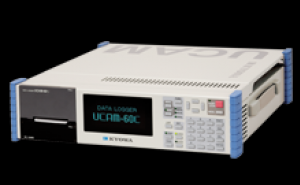
The data logger UCAM-60C M14 is an all-in-one measuring instrument developed in full pursuit of easier field measurement.
It has easy-to-operate keys, a bright readable display providing understandable presentation and a printer for immediate confirmation of measurement results.
【Data Loggers】
UCAM-60C-AC M14 (AC, UCS-60B: Optional, operation keys, built-in display, printer)
UCAM-60C-DC M14 (DC, UCS-60B: Optional, operation keys, built-in display, printer)
UCAM-65C-AC M14 (AC, UCS-60B: Standard, PC-controlled)
UCAM-65C-AC-0 M14 (AC, UCS-60B: Optional, PC-controlled)
UCAM-65C-DC M14 (DC, UCS-60B: Standard, PC-controlled)
UCAM-65C-DC-0 M14 (DC, UCS-60B: Optional, PC-controlled)
【Dedicated Scanners (Optional) 】
USS-61B (TEDS compatible) *
The dedicated scanner measures 10 channels/unit.
The main unit accommodates up to 3 dedicated scanners.
USS-62B (With NDIS4102 (7 pins) connectors, TEDS compatible) *
The dedicated scanner measures 10 channels/unit.
The main unit accommodates up to 3 dedicated scanners.
USS-63B (For civil engineering, with lightning arresters, TEDS compatible) *
The dedicated scanner measures 10 channels/unit.
The main unit accommodates up to 3 dedicated scanners.
* TEDS compatible function is made effective by connecting TEDS installed sensor through NDIS4102 (7 pins) connector.
【External Scanners】
The main unit is connected to the following scanners via the optional scanner interface.
USB-70B (Via scanner interface USI-67A)
【Scanner Interfaces 】
USI-67A for USB-70B
【External I/O Unit】
UIO-60A
【Control Software】
UCS-60B
Specifications
|
Measuring Targets
|
Strain gages
Strain-gage transducers
DC voltage-output instruments
DC current-output instruments
Civil engineering transducers with a thermal sensor
Potentiometer sensors
Thermal sensors (Thermocouples and platinum resistance thermometer bulbs)
|
|
Connectable Scanners
|
USS-61B, USS-62B, USS-63B
(Dedicated scanners, mounted on top of the UCAM-60C M14)
The main unit is connected to the following scanners via the optional scanner interface (USI-67A).
USB-70B series (via USI-67A)
|
|
Channels
|
Max. 30 with dedicated scanners
Max. 1000 with external scanners connected
Max. 1000 with dedicated scanners and external scanners connected
|
|
Input Terminals
|
Can connect to lead wires through either soldering or screwing.
(Screw: M3 with metal plate)
NDIS4102 (7 pins) connectors (USS-62B)
|
|
Switching Terminal
|
Semiconductor relays
|
|
Scanning Speed
|
50 ms/channel (Standard mode)
0.28 s/channel (High-resolution mode)
20 ms/channel (High-speed mode)
-------Scanners--------------------Line Frequencies------------
Dedicated scanner (Standard mode)
50 Hz Zone: 50 ms/channel
60 Hz Zone: 50 ms/channel
Dedicated scanner (High-resolution mode)
50 Hz Zone: 0.28 s/channel
60 Hz Zone: 0.28 s/channel
Dedicated scanner (High-speed mode)
50 Hz Zone: 20 ms/channel
60 Hz Zone: 20 ms/channel
USB-70B (Standard mode only)
50 Hz Zone: 60 ms/channel
60 Hz Zone: 58.4 ms/channel
[Note 1]
Scanning speeds stated above are standard maximum speeds in respective modes.
Besides these, the following speeds are set for each individual channel:
0.28 s, 0.5 s, 1 s, 2 s, 5 s, and 10 s.
[Note 2]
High-resolution mode and high-speed mode are selectable for dedicated scanners only.
[Note 3]
High-resolution mode is individually switchable for desired channels.
High-speed mode is only collective switching for all channels of dedicated scanners.
Repeat measurement interval time
= (Number of Measuring channels × scanning speed)
+ data processing time (2 to 20 s)
*Data processing time is indeterminate, changed by measurement setting and environment.
-------Measuring Targets--------------------Scanning Speed------------
Strain (Gage & transducer)
Standard Mode (50 ms/channel)
High-resolution Mode (0.28 s/channel)
High-speed Mode (20 ms/channel)
Voltage/current-output sensor
Standard Mode (50 ms/channel)
High-speed Mode (20 ms/channel)
Civil engineering transducer
Standard Mode (50 ms/channel)
Temperature sensor (TC, Pt)
Standard Mode (50 ms/channel)
Potentiometer sensor
Standard Mode (50 ms/channel)
High-speed Mode (20 ms/channel)
[Note 1]
High-resolution mode is available only with full bridge system.
[Note 2]
High-speed mode is available full bridge system, voltage, current, and potentiometer sensor.
|
|
Operating Modes
|
Real-time
Monitor
Automatic (Interval measurement)
|
|
Measurement Functions
|
Initial (Initial values are measured and stored in internal memory.)
Measure (Initial values are subtracted from original values.)
Original (Raw values are measured without subtraction of initial values.)
Easy Measure (Auto zero balancing function is activated.)
*The selected function is applied to all channels.
|
|
Coefficient Calculation Function
|
Multiplication by calibration coefficient
Calibration by TEDS
Conversion of measured values to physical quantities
Scaling
Correction
|
|
Unit
|
59 units
|
Automatic Measurement Function
|
Interval Measurement
|
Measurement is automatically performed at preset time intervals.
|
|
Trigger Measurement
|
A relative value (certain changing quantity) or an absolute value triggers measurement.
|
|
Trigger Interval Measurement
|
Combination of trigger measurement and interval measurement.
|
|
Storage
|
Internal memory
Capacity: Approx. 1.8 GB
|
Strain Measurement (Standard Mode)
|
Constant Voltage Excitation
|
Approx. 2 or 5 VDC
|
|
Constant Current Excitation
|
Approx. 5.7 mA (Bridge resistance 350 Ω)
Approx. 16.7 mA (Bridge resistance 120 Ω)
|
|
Scanning Speed
|
50 ms/channel
|
|
Gage Factor
|
2.00 fixed
(Coefficient calculation function enables correction with 2.00/Ks.)
|
|
Initial Value Memory Range
|
Same as measuring range.
|
|
Measuring Range, Resolution and Accuracy
|
Measuring Range: 0 to ±50 k ×10-6 strain
Resolution: 1 ×10⁻⁶ strain
Accuracy: ±(0.05% of reading +1) ×10-6 strain
Measuring Range: ±50 k to ±500 k ×10-6 strain
Resolution: 10 ×10-6 strain
Accuracy: ±(0.05% of reading +10) ×10-6 strain
*Resolution and accuracy be automatically changed by Autorange function.
|
Strain Measurement (High-resolution Mode)
|
Constant Voltage Excitation
|
Approx. 5 VDC
|
|
Constant Current Excitation
|
Approx. 16.7 mA (Bridge resistance 350 Ω)
|
|
Scanning Speed
|
0.28 s/channel
|
|
Initial Value Memory Range
|
Same as measuring range.
|
|
Gage Factor
|
2.00 fixed
(Coefficient calculation function enables correction with 2.00/Ks.)
|
|
Measuring Range, Resolution and Accuracy
|
Measuring Range: 0 to ±20 k ×10-6 strain
Resolution: 0.1 ×10⁻⁶ strain
Accuracy: ±(0.05% of reading +0.3) ×10-6 strain
Measuring Range: ±20 k to ±200 k ×10-6 strain
Resolution: 1 ×10⁻⁶ strain
Accuracy: ±(0.05% of reading +3) ×10-6 strain
Note 1: Available only with full bridges system.
Note 2: Bridge resistance should be 120 to 1000 Ω for bridge excitation with constant voltage.
Note 3: Bridge resistance should be 350 Ω for bridge excitation with constant current.
[Measuring range]
0 to ±15000 ×10-6 strain
0 to ±150000 ×10-6 strain
Note 4: Available only with dedicated scanners.
Note 5: Resolution and accuracy be automatically changed by Autorange function.
|
Strain Measurement (High-speed Mode)
|
Constant Voltage Excitation
|
Approx. 2 VDC
|
|
Constant Current Excitation
|
Approx. 5.7mA (Bridge resistance 350 Ω)
Approx. 16.7mA (Bridge resistance 120 Ω)
|
|
Scanning Speed
|
20 ms/channel
|
|
Gage Factor
|
2.00 fixed
(Coefficient calculation function enables correction with 2.00/Ks.)
|
|
Initial Value Memory Range
|
Same as measuring range.
|
|
Measuring Range, Resolution and Accuracy
|
Measuring Range: 0 to ±50 k ×10-6 strain
Resolution: 1 ×10⁻⁶ strain
Accuracy: ±(0.08% of reading +3) ×10-6 strain
Measuring Range: ±50 k to ±500 k ×10-6 strain
Resolution: 10 ×10-6 strain
Accuracy: ±(0.08% of reading +30) ×10-6 strain
[Note 1]
Available only with full bridges system (120 to 1000 Ω).
[Note 2]
Available only with dedicated scanners.
[Note 3]
Resolution and accuracy be automatically changed by Autorange function.
|
Voltage Measurement (Standard Mode)
|
Scanning Speed
|
50 ms/channel
|
|
Initial Value Memory Range
|
Same as measuring range
|
|
Measuring Range, Resolution and Accuracy
|
Channel Mode: V/500mV
Measuring Range: 0 to ±50.000 mV
Resolution: 1 μV
Accuracy: ±(0.05% of reading +0.003) mV
Input Resistance: 10 MΩ or more
Channel Mode: V/500mV
Measuring Range: ±50.00 to ±500.00 mV
Resolution: 10 μV
Accuracy: ±(0.05% of reading +0.03) mV
Input Resistance: 10 MΩ or more
Channel Mode: V/50V
Measuring Range: 0 to ±5.0000 V
Resolution: 100 μV
Accuracy: ±(0.05% of reading +0.0002) V
Input Resistance: 1 MΩ or more
Channel Mode: V/50V
Measuring Range: ±5.000 to ±50.000 V
Resolution: 1 mV
Accuracy: ±(0.05% of reading +0.002) V
Input Resistance: 1 MΩ or more
*Resolution and accuracy be automatically changed by Autorange function.
|
Voltage Measurement (High-speed Mode)
|
Scanning Speed
|
20 ms/channel
|
|
Initial Value Memory Range
|
Same as measuring range
|
|
Measuring Range, Resolution and Accuracy
|
Channel Mode: V/500mV
Measuring Range: 0 to ±50.000 mV
Resolution: 1 μV
Accuracy: ±(0.08% of reading +0.006) mV
Input Resistance: 10 MΩ or more
Channel Mode: V/500mV
Measuring Range: ±50.00 to ±500.00 mV
Resolution: 10 μV
Accuracy: ±(0.08% of reading +0.06) mV
Input Resistance: 10 MΩ or more
Channel Mode: V/50V
Measuring Range: 0 to ±5.0000 V
Resolution: 100 μV
Accuracy: ±(0.08% of reading +0.0006) V
Input Resistance: 1 MΩ or more
Channel Mode: V/50V
Measuring Range: ±5.000 to ±50.000 V
Resolution: 1 mV
Accuracy: ±(0.08% of reading +0.006) V
Input Resistance: 1 MΩ or more
[Note 1]
Resolution and accuracy be automatically changed by Autorange function.
[Note 2]
Available only with dedicated scanners.
|
Current Measurement (Standard Mode)
|
Scanning Speed
|
50 ms/channel
|
|
Initial Value Memory Range
|
Same as measuring range
|
|
Measuring Range, Resolution and Accuracy
|
Channel Mode: I/50 mA
Measuring Range: 0 to ±50.00 mA
Resolution: 10 μA
Accuracy: ±(0.05% of reading +0.01) mA
[Note 1]
External shunt resistor (high-accuracy 250 Ω) is required.
[Note 2]
Stated accuracy does not include the resistance error of the external shunt resistor.
|
Current Measurement (High-speed Mode)
|
Scanning Speed
|
20 ms/channel
|
|
Initial Value Memory Range
|
Same as measuring range
|
|
Measuring Range, Resolution and Accuracy
|
Channel Mode: I/50 mA
Measuring Range: 0 to ±50.00 mA
Resolution: 10 μA
Accuracy: ±(0.08% of reading +0.01) mA
[Note 1]
Available only with dedicated scanners.
[Note 2]
External shunt resistor (high-accuracy 250 Ω) is required.
[Note 3]
Stated accuracy does not include the resistance error of the external shunt resistor.
|
Temperature Measurement with Thermocouple (Standard Mode)
|
Scanning Speed
|
50 ms/channel
|
|
Measuring Range, Resolution and Accuracy
|
【Type: K】
Measuring Range: −200.0 to 1230.0℃
Resolution: 0.1℃
Accuracy: ±0.7℃
Internal Reference Junction Compensator Accuracy: ±0.5℃
(With input terminal temperature balanced in an ambient)
(Temp. range of 0 to 50°C)
【Type: T】
Measuring Range: −200.0 to 400.0℃
Resolution: 0.1℃
Accuracy: ±0.7℃
Internal Reference Junction Compensator Accuracy: ±0.5℃
(With input terminal temperature balanced in an ambient)
(Temp. range of 0 to 50°C)
【Type: E】
Measuring Range: −200.0 to 660.0℃
Resolution: 0.1℃
Accuracy: ±0.5℃
Internal Reference Junction Compensator Accuracy: ±0.5℃
(With input terminal temperature balanced in an ambient)
(Temp. range of 0 to 50°C)
【Type: J】
Measuring Range: −200.0 to 870.0℃
Resolution: 0.1℃
Accuracy: ±0.6℃
Internal Reference Junction Compensator Accuracy: ±0.5℃
(With input terminal temperature balanced in an ambient)
(Temp. range of 0 to 50°C)
【Type: R】
Measuring Range: 0 to 1760.0℃
Resolution: 0.1℃
Accuracy: ±2.2℃
Internal Reference Junction Compensator Accuracy: ±0.5℃
(With input terminal temperature balanced in an ambient)
(Temp. range of 0 to 50°C)
[Note 1]
Accuracies do not include the internal reference junction compensator accuracy.
[Note 2]
The reference junction compensator is switchable between internal and external.
[Note 3]
Thermocouple resistance should be 1 kΩ or less.
|
Temperature Measurement with Civil Engineering Transducers with a Thermal Sensor (Standard Mode)
|
Scanning Speed
|
50 ms/channel
|
|
Measuring Range, Resolution and Accuracy
|
Measuring Range: −50.0 to 200.0℃
Resolution: 0.1℃
Accuracy: ±0.5℃
[Note 1]
Target physical quantity and temperature are measured in a single channel.
[Note 2]
Strain measuring range are the same as in strain measurement in standard mode.
|
Temperature Measurement with Platinum Resistance Thermometer Bulb (Standard Mode)
|
Scanning Speed
|
50 ms/channel
|
|
Measuring Range, Resolution and Accuracy
|
【Type: Pt100】
Measuring Range: −200.0 to 660.0℃
Resolution: 0.1℃
Accuracy: ±0.3℃
【Type: JPt100】
Measuring Range: −200.0 to 510.0℃
Resolution: 0.1℃
Accuracy: ±0.3℃
Note: Connection is 3-wire system.
|
Measurement with Potentiometer Sensor (Standard Mode)
|
Scanning Speed
|
50 ms/channel
|
|
Initial Value Memory Range
|
Same as measuring range
|
|
Sensor Power Supply
|
Approx. 2 VDC
|
|
Potentiometer Resistance
|
1 kΩ to 10 kΩ
|
|
Measuring Range, Resolution and Accuracy
|
Channel Mode: POT.
Measuring Range: 0 to ±50.00%
Resolution: 0.01%
Accuracy: ±0.1% FS
|
Measurement with Potentiometer Sensor (High-speed Mode)
|
Scanning Speed
|
20 ms/channel
|
|
Initial Value Memory Range
|
Same as measuring range
|
|
Sensor Power Supply
|
Approx. 2 VDC
|
|
Potentiometer Resistance
|
1 kΩ to 10 kΩ
|
|
Measuring Range, Resolution and Accuracy
|
Channel Mode: POT.
Measuring Range: 0 to ±50.00%
Resolution: 0.01%
Accuracy: ±0.1% FS
Note: Available only with dedicated scanners.
|
|
Internal Timer
|
Real time clock is built-in. (Battery backup)
|
|
Display
|
Fluorescent display tube
128 × 64 dots
|
|
Printer
|
Printing: Thermal
Paper width: 58 mm (24 characters/line)
Printing speed: 60 mm/s (Max.)
|
|
Interface
|
RS-232C
LAN (10BASE-T/100BASE-TX)
USB2.0 (Collects measurement data by USB Flash Drive.)
*1: Measurement data cannot be saved directly to USB memory.
*2: USB Flash Drives
Capacity: 32 GB or less
File Format: FAT32
*3: Recommend USB Flash Drives: GH-UFI-XSD2G
(Manufacturer: GREENHOUSE)
|
|
File Conversion
|
Binary measurement data can be converted to CSV.
|
|
Self Diagnosis Functions
|
Checks display, printer, bridge excitation, leadwire-off, input/output resistance, insulation resistance, mode, etc.
|
|
TEDS
|
[Interface]
IEEE1451.4 Mixed Mode Transducer Interface Class2
[Applicable sensor]
Should have information written in accordance with IEEE template No.33.
Cable length should be 30m or less.
*With dedicated scanner USS-61B/62B/63B.
|
|
Operating Temperature
|
0 to 50ºC
|
|
Operating Humidity
|
20% to 85% (Non-condensing)
|
|
Storage Temperature
|
-20 to 60ºC
|
|
Setting Maintenance Function
|
ACOM at measurement circuit is switchable between floating and GND connect.
|
|
Power Supply
|
100 to 240 VAC (AC-operated version)
10 to 16 VDC (DC-operated version)
*DC operated version has power control function.
|
|
Current Consumption
|
100 VAC: 0.5 A or less (With 3 dedicated scanners mounted)
12 VDC: 4.0 A or less (With 3 dedicated scanners mounted)
|
|
Dimensions
|
360 W ×88 H ×400 D mm (Excluding protrusions)
|
|
Weight
|
Approx. 6.3 kg (Excluding scanner)
Approx. 9.6 kg (With 3 dedicated scanners USS-62B mounted)
|
|
Standard Accessories
|
AC power cable P-18 (With 2-pin conversion plug CM-52)
(AC-operated version)
DC power cable P-76
(DC-operated version)
Recording paper UCAM-60A-RP (1 roll)
Screwdriver
Spare fuse
CD-R (Instruction Manual)
Ground wire P-72
|
|
Optional Accessories
|
Recording paper UCAM-60A-RP (10 rolls/pack)
|
SANTA TECHNOLOGY CO.,LTD. (Head Office)
35/218 Moo. 2, Leabkhlongsam Rd., Khlongsam, Khlongluang, Pathumthani 12120
Call 02-101-3454 ,089-006-2766
Fax 02-101-3453
Mail. santatech@gmail.com
Line : @santatech
Web : https://santatechnology.com/


 ติดต่อทาง Line
@santatech
ติดต่อทาง Line
@santatech
 ติดต่อทางอีเมล์
santatech@gmail.com
ติดต่อทางอีเมล์
santatech@gmail.com
 ติดต่อทางโทรศัพท์
02-1013454
ติดต่อทางโทรศัพท์
02-1013454
